AR glasses USB protocols: the Good, the Bad and the Ugly
I've just finished implementing the third completely different USB protocol for my open-source AR glasses drivers project, so it's time to summarize my findings, and drop some fun facts on you in the process.
Background
All three glasses use USB-C for all their communication, and I guess not everyone's a USB expert, so here's a little introduction of the important part
USB-C plug
First of all, USB-C is the connector. It's often confused with USB3, the electrical and low-level transmission specification, but they are somewhat orthogonal.

Pins important for us:
| Pin | Purpose |
|---|---|
| D+, D- | USB2 pins (duplicated to be symmetric) |
| CC1, CC2 | Configuration |
| TX1, RX1, TX2, RX2 | 4 high speed differential lanes |
The "configuration" pins are used to to tell the other side what the plug orientation actually is, set up USB-PD (100W charging), and, importantly, Alternate Mode.
USB2 and 3
As you could see in the pinout, the USB-C connector contains a full USB2 pinset and additional 4 differential lanes for USB3.
It is possible to use these two in parallel, and the USB2 and USB3 buses will
show up as two different, independent devices with lsusb.
Alternate Mode
For our purposes, DisplayPort-over-USB-C Alternate Mode is the most important, since all the AR glasses we will be looking at use this to deliver the image to the device.
This is done by using 2 or 4 "SuperSpeed" lanes for DP data directly:
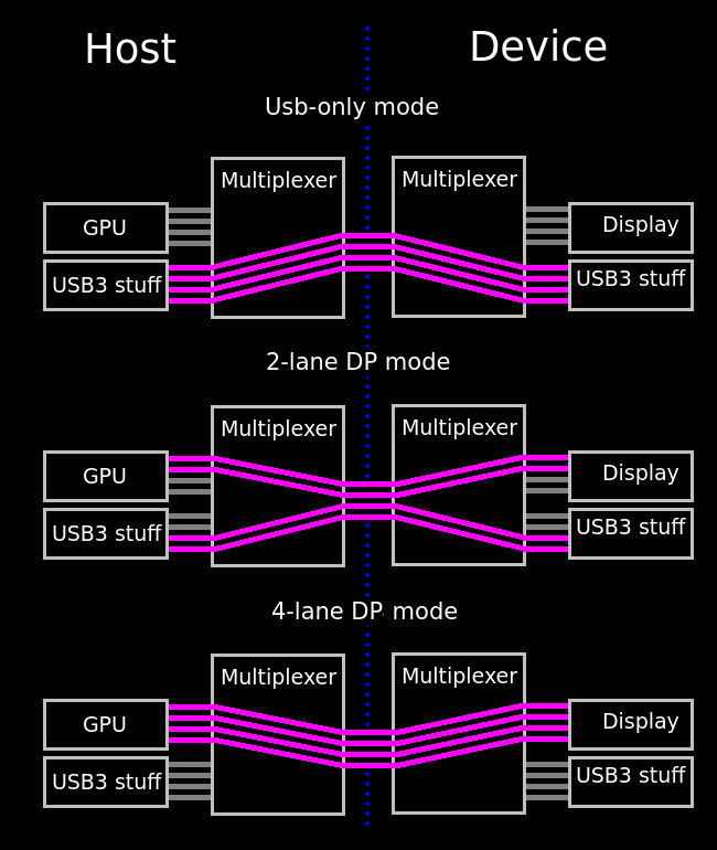
In the first two cases we still have some USB3 communication, but in the last case only the USB2 can be used. This is why with some docks, if you plug in the displays, even the USB-C and the 9 pin blue Type-A ports "switch back" to USB2 only.
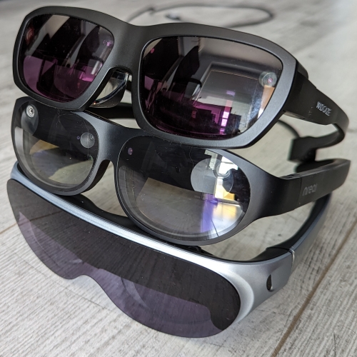
The Good: Rokid Air
By good, I mean a very easy to implement protocol. The glasses themselves are great for the price, but they are at most OK otherwise. The SDK was easy enough to obtain, and getting the protocol bits out was also very straightforward, so I'll omit these steps from the story.
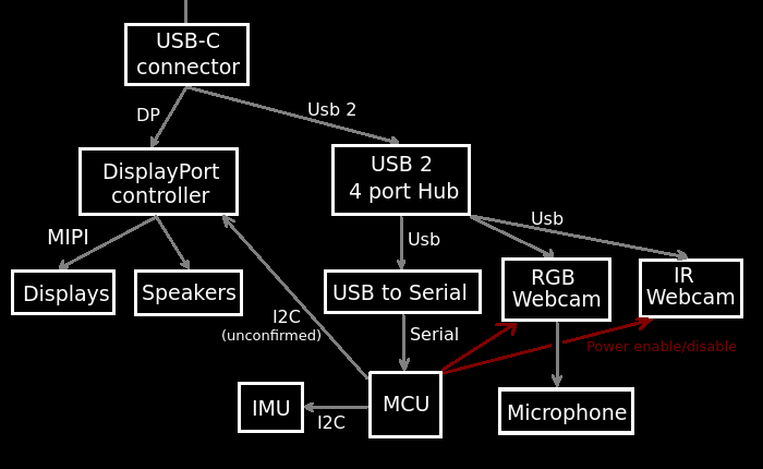
Inside the glasses, we can find (among other things)
- The two displays, driven by a single
DP => MIPIconverter. It can operate in either 2D mode, where both displays show the same FullHD picture, or 3D Side-By-Side (SBS) mode, where the DP chip registers as a 3840x1080 display on the DP bus, and shows the two halves on the two displays. - A microphone
- An Inertial Measurement Unit (IMU), our main target, because it senses acceleration (including gravity) and rotation at a high rate (440Hz in case of the Rokid Air)
- A microcontroller (MCU) to connect to the computer and control the rest of the chips (e.g. get IMU data or switch to SBS mode)
As far as I can tell, this is how they are all connected:

The MCU comes up with VID=04d2, PID=162f and four USB interfaces:
- Audio Control
- Audio Data
- HID (subclass=0) with endpoint address
0x2and0x82 - HID (subclass=1, boot) with endpoint addresses
0x1and0x81
IMU data is transferred on the 0x2/0x82 endpoint. In the SDK
this is not detected based on classes or name or anything, the SDK simply
chooses the endpoint based on its number (0x82).
The Rokid Air MCU protocol
The USB protocol here consists of two main classes:
- Control messages, including getting device data like screen configuration
- Event messages
Control messages are sent and received with control transfers, with the
request, index and data parameters set to the correct values. The request
mode is always type=Vendor, recipient=Device.
| Command | Request | Index | Value | Data |
|---|---|---|---|---|
| GetDisplayMode | 0x81 | 0x01 | 0x00 | First byte is 0 in 2D mode, 1 in 3D mode |
| SetDisplayMode | 0x01 | 0x01 | 0x00: 2D 0x01: 3D |
[0x01] |
| GetBrightness | 0x82 | 0x02 | 0x00 | First byte is the brightness (1-7) |
| SetBrightness | 0x02 | 0x02 | Brightness | [0x01] |
| GetSerialNumber | 0x81 | 0x00 | 0x100 | 0x40 bytes, zero terminated string |
There are a lot of other commands, like reboot, file storage, and raw I2C
operations, but I didn't really mess with those, as the above is more than
enough. If anyone's interested, these can be easily obtained from the native
SDK .so files.
Sensor data arrives with interrupt transfers, like regular HID. While it would
be great to use hidapi, thenwe cannot use the vendor-specific control
transfers, since libusb takes the device away from the Linux
hidraw driver. Using hidapi with the libusb backend makes little sense,
as it would be just another wrapper with an additional thread.
Anyway, on the interrupt input endpoint, we get packets like this with around 400Hz:
$ cat /dev/hidraw5 | hexdump -f compact

04 01 e4 00 00 00 00 00  00 a9 3a 71 00 00 00 00
00 01 00 00 00 94 0c 38  be 12 c7 16 41 36 f6 0d
40 f4 00 00 00 00 00 00  00 28 5f 00 20 73 c1 02
08 00 00 01 00 00 00 00  00 00 00 00 00 00 00 00

04 02 e5 00 00 00 00 00  00 71 43 71 00 00 00 00
00 01 00 00 00 1e d4 55  bc 84 38 39 bb f0 fc 47
3a f4 00 00 00 00 00 00  00 28 5f 00 20 73 c1 02
08 00 00 01 00 00 00 00  00 00 00 00 00 00 00 00

04 03 d7 01 00 00 00 00  00 04 f9 d4 0f 00 00 00
00 00 00 00 00 8b b8 a0  41 18 90 20 c2 12 01 2e
c1 00 00 00 00 00 00 00  00 00 00 00 00 00 00 00
00 00 00 00 00 00 00 00  00 00 00 00 00 00 00 00

02 0b 11 04 00 00 00 00  00 00 00 00 00 00 00 00
00 00 00 00 00 00 00 00  00 00 00 00 00 00 00 00
00 00 00 00 00 00 00 00  00 00 00 00 00 00 00 04
00 00 00 00 00 00 00 00  00 00 00 00 00 00 00 00
The packet format is incredibly simple. First, let's see the sensor data packets (where the first byte is 0x04):
| Index | Bytes | Description |
|---|---|---|
| 0x00 | 1 | Sensor data marker |
| 0x01 | 1 | Sensor type (1: accelerometer, 2: gyro, 3: magnetometer) |
| 0x02 | 1 | Sequence number |
| 0x03 | 1 | Magnetometer accuracy |
| 0x09 | 4 | Timestamp (little endian) |
| 0x15 | 3x4 | x, y and z reading in f32 format |
The "misc" packet (first byte == 2) is even simpler: byte 0x2f is nonzero
if the button is pressed, and byte 0x33 is nonzero if the proximity sensor
does not detect a forehead. It is also sent periodically.
The Bad: Mad Gaze Glow Plus
This was actually the first glasses I bought, as it was somewhat cheap, contained both an IMU and cameras. Unfortunately it turns out the company went silent in 2021, after rugpulling a kickstarter campaign. The whole glasses feels super cheap and plastic-y, and has that characteristic plastic squeak when you open the arms.
This made it somewhat hard to find an SDK. I actually had to scour the net for an application to extract the SDK from. Once I found one, I plugged it to decompiler.com, and got some good and bad news:
- The good news: the whole SDK is in Java, no native component, so decompiling to source is going to be EZPZ
- The bad news:
USBSerial2.java
Yup, this is going to be one of those. As you might know, not all microcontrollers support USB out of the box. In these cases, the lazy thing to do is to buy one of those el-cheapo USB -> Serial converters and just use the serial port.
The architecture of the insides:
Let's unpack this absolute clusterfsck:
- USB hub: To be fair, this is a clever way of packing multiple functions in a single USB device and still have it supported by default drivers.
- USBSerial:
VID=04b4, PID=0002. It is immediately "recognized" by thecythermkernel module, which needs to be disabled, otherwise you cannot open the serial port. - Speakers on DisplayPort: DisplayPort can actually support 8 channel audio, which is sent as special packets during vsync
- Microphone on camera: To avoid having to add an audio chip, these absolute madmen just used an off-the-shelf webcam IC that had a microphone driver.
- Power to the webcams: Apparently you can only use one webcam at a time. I guess due to power constraints? In any case, you can switch with a special MCU command.
The Mad Gaze MCU protocol
So back to the serial thing. Remember that I only had the glasses, some
decompiled SDK, but I couldn't run anything. I went a bit barbaric: set
up the serial as it is in the SDK, and just piped urandom straight into
it and see if it answers.
It actually did. With an error, but still, what a relief. I quickly correlated which bytes caused the answer, and determined that it was something about the 0x3a byte.
In any case, the working protocol implementation has two layers: the framing, and the actual contents. Frame format:
| Index | Bytes | Description |
|---|---|---|
| 0x00 | 1 | Start byte: 0x3a (the : character) |
| 0x01 | 3 | Command |
| 0x04 | 1 | Length (including headers and footers, so len(data) + 5) |
| 0x05 | 2 | Session Id (used for correlating requests and responses, can be anything) |
| 0x07 | n | Command data |
| n + 0x07 | 2 | CRC16 (not actually checked by the glasses if set to 0000) |
| n + 0x09 | 1 | Magic fixer byte |
..."magic fixer byte"??? Yeah. There are no brakes on this incompetence train.
Since apparently 0x3a is an important sync byte, it would be bad if it
was present in the packet. So what they did is if they find a 0x3a in the
data, they replace it with 0x3b and record the byte index (so the glasses
can fix that byte). If there are no 0x3a bytes, this is set to 0xff.
I just added an assert into the code to check for this byte during sending, and I don't even parse this part in the reply. No problems yet.
Now, you might ask, what are the commands?
| Command | Id | Data out | Data in |
|---|---|---|---|
| Get serial | GSN |
[] | Serial number as string |
| Get display mode | G3D |
[] | Byte 0: is display status (is it working or not) byte 1: 3D mode enabled |
| Set display mode | G3D |
[3D mode byte] | Should be [0] |
| Enable camera | OPC |
[Camera index] | Should be [0] |
| Disable camera | CLC |
[Camera index] | Should be [0] |
| Read I2C | I2R |
[1, address, register, 0, length] | 5 bytes of junk I don't care about, followed by the read data |
| Write I2C | I2W |
[1, address, register, 0, length, ..data..] | Byte 4 is should be 0 |
I2C
Wait, where are the IMU commands? Ohhohhoo, we're going to rawdog I2C for that.
There are two I2C devices we care about: the IMU (BMI160) and the
magnetometer (AK09911). The Java SDK had a minimal implementation of
setting it up and then polling it, and I guess I didn't have a choice either
So right now my AR driver repo has what is basically the most minimal BMI160 driver for Rust that is out there. Embedded devs rejoice. Or not.
Since we are doing USB => Serial => I2C and back roundtrips,
speed and latency are not great. In fact, polling frequency is only about
100Hz, and the only reason I don't lose data and it's somewhat
accurate is because I use the IMU in FIFO mode.
On the bright side, I have fine control over the built-in filter of the IMU.
It's usual to have minimal code on the microcontrollers of these cheap AR glasses, because writing firmware is harder than writing Java or C++, and this way things like AHRS fusion can be in the SDK, and can be regularly and safely updated.
But putting the whole I2C handling into the SDK takes the cake. It
is to the detriment of quality here because of the bandwidth and
latency.
The Ugly: Nreal Light
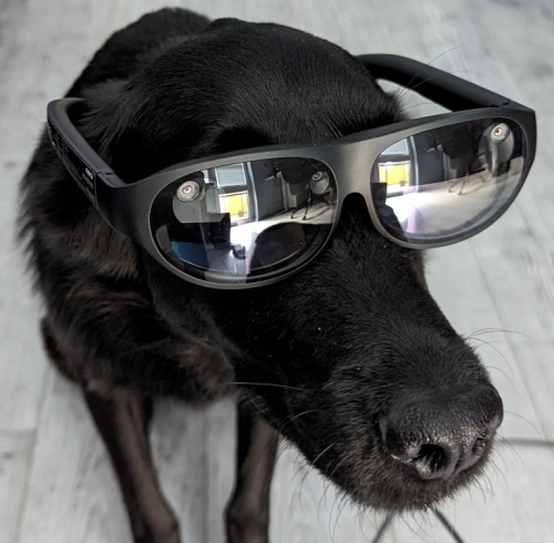
The build quality of these glasses is actually pretty good, and they almost look like bulky sunglasses, and not full-on 90s cyberpunk disco shades.
These were the only cheap glasses I could find that had both camera (it has three, in fact!) and IMU. The architecture and the protocol are somewhat reasonable too.
Let's start with the architecture:
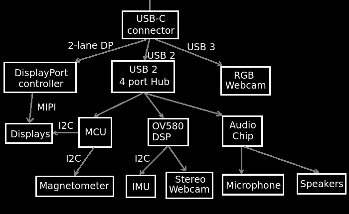
This is, again, a bit complicated, but also uncomplicated. The interesting bits are
- Both the USB2 and USB3 buses are in use: As noted above, these are
present as two completely separate buses in
lsusb, which looked weird at first. - 2-lane DP: Since 2 of the lanes are used by a (very good quality)
webcam, we are only left with 2 lanes worth of DisplayPort. This halves
bandwidth. It can still do
1080p@60withDisplayPort 1.2, and more than2x1080p@60withDisplayPort 1.4. Unfortunately my USB-C DP testphone is a Samsung Galaxy S9+, which only supports DP1.2. My main phone, a Pixel actually has hardware for USB-C DP, but those pricks at Google hard disabled the functionality from software. - IMU not on MCU: Spoilers :)
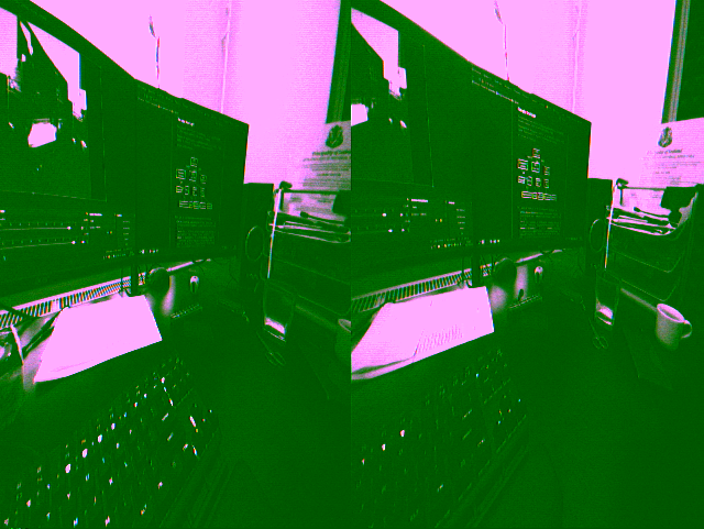
- OV580: The OV580 is a weird beast: it's a somewhat powerful DSP that is able to handle multiple synchronized cameras and put their data on USB. On the Nreal Light, it is used to put the stereo cameras' pictures on a single image and stream it to the PC at 60Hz raw YUV
Here's what that image looks like:
The quest for IMU data
I began this project just like the other two: got the glasses, downloaded the SDK (or more precisely, extracted it from an APK), and got to static analysis. I don't have a compatible phone, or a Mac, so unfortunately packet capture was out of the question.
Now, the SDK shared lib is 25 megabytes of statically linked, vtable-infested mess. I counted something like 5 GPL violations, BTW, so maybe I should've asked for the source. Reversing it was a pain, so I gave up after some 2 days and instead focused on the included firmware binary.
The firmware was a much tamer beast, just a cookie-cutter 70KB STM32F4 image with a very minimal header. There were some helpful log and USB response strings, but ...
... no strings related to the IMU. There were some about the magnetometer, but no IMU. Bad sign. Maybe these glasses don't even use the IMU for head tracking? There are some pretty good cameras on board so maybe it's SLAM only.
I reversed most of the firmware. No signs of IMU handling on I2C, and the SPI port of the STM32 was not used at all. I even patched the firmware to have raw I2C commands, but found no IMU chips.
Reddit and Discord
I got very fed up with this development. The manufacturer promised an IMU, but alas, no IMU to be found! I was so annoyed that I actually registered to reddit and made a rant post just so I could get it out of my system.
Secretly though, I hoped that I was wrong and they could point me in the right direction.
The dev Discord was a pleasant surprise too, people there were friendly and helpful, and provided a ton of great information.
After some time I got some logs from someone with an Nreal Light that had strings I've seen previously:
[INFO] [NRSDK] IMU starting
[INFO] [NRSDK] Generic Control callback true
[INFO] [NRSDK] IMU started
[INFO] [NRSDK] NRTracking RUN!
[INFO] [NRSDK] IMU Generic Protocol version : 20200323
I'll be damned. There is an IMU, I just didn't find it. Maybe it's in the audio chip? Or the OV580? Both had Nreal-customized firmware, but it seemed like an incredibly weird thing to do.
I tried putting both binaries into ghidra without much luck, but this was actually
a good thing, because I started looking elsewhere: apparently there was a beta
version of a Mac SDK.
And would you look at that, the .dylib in the Mac SDK had full symbols, i.e.
the thing could be decompiled basically to source, with names and types and all.
And then I saw it...
ImuDataProtocol_Generic_Ov580
Oh my God, they actually did put the IMU control in the camera DSP chip. I was angry, relieved and disgusted at the same time. After finding this, it was about a day's worth of reversing the relevant code (with all the vtables in the world), I assembled the magic 3 bytes that needed to be sent to the previously mysterious OV580 HID device, and it immediately started bombarding me with IMU data.
I made a correction post on Reddit and got to work on a proper driver code this time.
The IMU protocol
Apparently Nreal really loves proper HID, so they actually made it so that all
their protos can be used with normal hidapi. It's good news, since that library
is more performant and way easier to use than libusb (I first tried to implement
the driver with libusb, but then switched to hidapi,
and it made the code so much simpler)
In the IMU's case, unlike the Rokid, which give you all the data without doing anything, you actually have to ask for it, by writing some command bytes to the HID channel. The message format looks like this:
| Index | Bytes | Description |
|---|---|---|
| 0x00 | 1 | Packet type (command: 0x02) |
| 0x01 | 1 | Command |
| 0x02 | 1 | Command data |
The commands that are relevant for us:
| Command | Id | Command data |
|---|---|---|
| Get calibration file length | 0x14 | Calibration file id according to the SDK, doesn't seem to affect anything. Can be 0. |
| Get calibration file part | 0x15 | Should be block number. Doesn't do anything, can be 0. |
| Enable IMU stream | 0x19 | 0: disable, 1: Enable |
If anyone is here only looking for a magic byte string to send to the OV580 to get the
IMU stream, it's [0x02, 0x19, 0x01].
The responses to the commands come mixed with the IMU stream. Packets starting with 0x02 are command responses, packets starting with 0x01 are the IMU events.
The glasses-specific calibration file can be read by sending a 0x14 command, and then
sending 0x15 commands until it returns an error. The data can be easily reassembled, and
it will contain a json file with all kinds of goodies, like gyroscope bias, or display
lens misalignment.
IMU packet format (all integers are signed little endian):
| Index | Bytes | Description |
|---|---|---|
| 0x00 | 1 | Packet type (IMU data: 0x01) |
| 0x2A | 2 | Temperature (raw data from the ICM-20602) |
| 0x2C | 8 | Gyroscope timestamp (nanoseconds) |
| 0x34 | 4 | Gyroscope multiplier |
| 0x38 | 4 | Gyroscope divisor |
| 0x3C | 4 | Gyroscope X reading |
| 0x40 | 4 | Gyroscope Y reading |
| 0x44 | 4 | Gyroscope Z reading |
| 0x48 | 8 | Accelerometer timestamp (nanoseconds, always same as gyro timestamp) |
| 0x50 | 4 | Accelerometer multiplier |
| 0x54 | 4 | Accelerometer divisor |
| 0x58 | 4 | Accelerometer X reading |
| 0x5C | 4 | Accelerometer Y reading |
| 0x60 | 4 | Accelerometer Z reading |
To get the actual gyroscope reading in radians per second:
Gyroscope reading * Gyroscope multiplier / Gyroscope divisor * PI / 180
To get the accelerometer readings in m/s2:
Accelerometer reading * Accelerometer multiplier / Accelerometer divisor * 9.81
And that's it. A bit wasteful, but easy to implement, and if they decide to change the gyro or accelerometer precision, it could be automatically handled.
The MCU control protocol
The MCU protocol is also implemented over HID, commands are simple writes,
responses and events are simple reads, unfortunately the two are mixed together.
The packets are actually ASCII strings with human readable characters, and could be represented with this format string
"\x02:{type}:{cmd}:{data}:{timestamp:>8x}:{crc:>8x}:\x03"
Fun fact: \x02 and \x03 are "start of text" and "end of text" in the official ASCII table.
The timestamp is not checked for sent packets, but CRC is. And of course it's not the standard CRC32, but Adler's weird version. Fortunately this didn't need to be reverse engineered from scratch :)
Data is sometimes irrelevant, but in that case the SDK still puts a single byte in the packet, so it's probably checked. I put an "x" there in these cases.
There are some 50-100 commands in the firmware, the relevant ones are:
| Name | Type | cmd | Data |
|---|---|---|---|
| Get serial | 3 | C | "x" |
| Get firmware version | 3 | 5 | "x" |
| Set display mode | 1 | 3 | "1": 2D "3": 3D "4": 3D at 72Hz |
| Get display mode | 3 | 3 | "x" |
| "SDK works" | @ | 3 | "1" |
| Heartbeat | @ | K | "x" |
| Enable ambient light reporting | 1 | L | "0": Disable "1": Enable |
| Enable v-sync reporting | 1 | N | "0": Disable "1": Enable |
| Enable magnetometer | 1 | U | "0": Disable "1": Enable |
| Set brightness | 1 | 1 | 0-7, as ASCII string |
| Get brightness | 3 | 1 | "x" |
| Enable RGB camera | 1 | h | "0": Disable "1": Enable |
| Enable Stereo camera | 1 | i | "0": Disable "1": Enable |
The "SDK works" one time, and then a periodic heartbeat are important, since without these, if you switch to SBS mode, the display will switch off within 1 second.
Parsing the responses is left as an exercise to the reader :)
(Updated on 2024.06.03. Thanks to @HappyZ for several corrections)
Conclusion
There is none, actually. I just like to have a dedicated last chapter, like a footer.
Or a goodbye.
Reverse engineering an unknown CRC
Autocxx and g2o
If you need Augmented Reality problem solving, or want help implementing an AR or VR idea, drop us a mail at info@voidcomputing.hu