The animated company logo

You can probably see that the logo at the top left is animated. At least if your browser decided to cooperate. This was done by using a .webm (or .mp4) video instead of just a regular image.
But how was the logo made? The answer is not "with an image/video editing software a normal person would use"
The initial concept
When deciding on a company name, one of the main consideration was if it could have a cool logo. And VOID sounds pretty cool, so I checked google images:
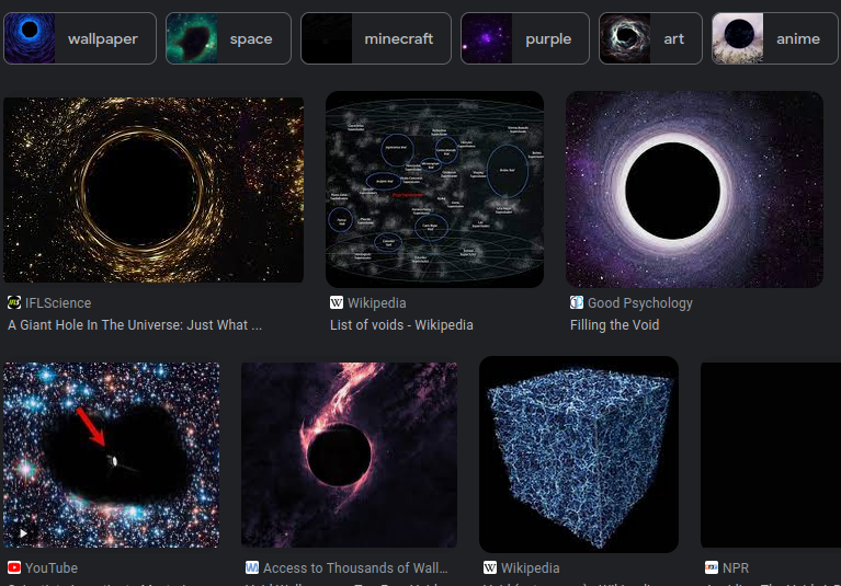
Ok, basically pre-Interstellar black hole. Sounds doable, and would look good in place of the O.
The concept art
Being the efficient person I am, I asked my wonderful wife to help me (i.e. create the logo for me). She's been playing around with Stable Diffusion lately, so I guessed it would be a few minutes of prompt engineering.
We went through some iterations, with me being the worst kind of customer ("hmm, this isn't what I wanted, can you make it bluer?" x 100), and this was the final result before she gave up:

As you can see I kept the font, it was a great find (and funnily enough, it was made in 1998, exactly the date where I get my retro-futuristic style ideas from).
But the swirl could be made better.
Note that this shows that the AI generators are good concept art and sketching tools, but fine tuning is basically impossible, you will always have to do manual work.
GIMP
The next day, I decided to finally install GIMP, the vim of image editors. I hate that software, last time I used it was some 8 years ago, and gave up when I couldn't find how to make a straight line, and installed KolourPaint instead.
Turns out, GIMP is not that bad nowadays, and is actually somewhat discoverable.
I had a concept of what to do too: create a simple starburst pattern and twist it.
- Generate some Perlin noise *
- Apply a gradient
- Convert to polar coordinates
- Apply twist filter
- Do some color mapping
*(I used to develop games, and once you find out about Perlin noise, you will do everything with it. It's the absolute hottest code path in Stickman Warfare )
So first step, noise. My GIMP's Perlin noise looks buggy, it leaves a kind of square pattern:
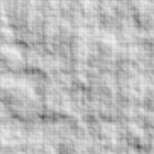
I found another one, called "Solid noise" which looks very similar to what I know as Perlin noise:
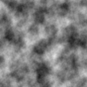
Now if we stretch it out a bit and apply polar coordinates, you will see where we are going:
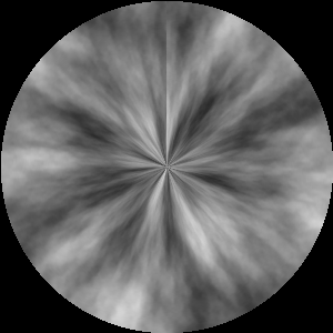
Well, maybe not. Let's apply a nice custom gradient (found as an alternative tool under the paint bucket... did I ever tell you I hate GIMP?) and then redo the polar coordinates:
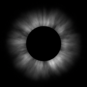
Now just a "Whirl and pinch" and color mapping, and we recreated the logo concept:
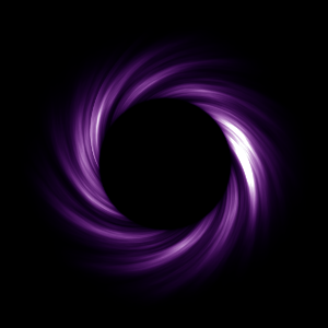
Looks... OK.
Now here's a problem: if I want to tweak any of these transformations, I have to go through all of them manually. And I want to do a lot of tweaks, this is an important logo.
There are a few solutions: scripting GIMP or maybe redoing it in Blender or a similar node-based texture generator. Both sounds like a lot of learning, so
Let's generate it in python
Or as Aphyr put it, let's pull a logo out of the void.
OK, so let's start with some scaffolding. Once you have a pypy virtualenv (otherwise the rendering takes days) and pypng installed into it, we can have a basic framework:
1 2 3 4 5 6 7 8 9 10 11 12 13 14 15 16 17 18 19 20 | |
Which generates this exquisite piece of art:

pixel_value(x,y) is what we are going to extend here. It gets the X and Y coordinates
as 0..1 ranges, and has to output R, G, B and A components as a 0..1 float. This is very
similar to what pixel shaders do, and this is because I wanted a familiar environment.
(This is why the above picture might look familiar. It's one of those typical shader
tutorial screenshots)
Ok, so what was the next GIMP step? Ah yes, Perlin noise. I won't bore you with the details, there are a metric fsckton of Perlin noise tutorials and libraries out there. I haven't found any in python to my liking, so what I've done is rewritten the old Delphi version (which I think I've got from a gamedev forum in 2007?) in python:
1 2 3 4 5 6 7 8 9 10 11 12 13 14 15 16 17 18 19 20 21 22 23 24 25 26 27 28 29 30 31 32 33 34 35 36 37 38 39 40 41 42 43 44 45 46 47 48 49 50 51 52 53 54 55 56 57 58 59 60 61 62 63 64 65 66 | |
I'm not going to explain the whole code, the gist is that complex_noise()
is a tiling Perlin noise generator which generates a float between -1..1.
If we directly plug it into pixel_value, we get this:
1 2 3 4 5 6 | |

Looks familiar, isn't it?
Now let's do the polar coordinate transformation:
1 2 3 4 5 6 7 8 9 10 11 12 13 14 15 16 17 | |

Hehhey, noice. And notice that it doesn't even have the black area around the unit circle. This is because the Perlin noise generator is tiling: if gives back the same value at (0.5; 0.7) and (0.5;1.7).
Okay, a few more steps. First, the gradient. Now... this code is not the most optimal... or pretty... but as long as the rendering runs in seconds, and tweaking is easy, I don't actually care.
1 2 3 4 5 6 7 8 9 10 11 12 13 14 15 16 17 18 19 20 | |

Very spooky. We are at the final stretch. I added a non-linear twirl to it. With a simple twirl, you just add the distance to the angle and that's it, you get a spiral. With this 0.3th power, we can simulate the "virtual material" acquiring speed.
1 2 3 4 5 6 | |

And finally, the color mapping. We want to keep the white white (so value=1 should be RGB(1,1,1)), the middle somewhat purple, and the tails bluish. There are many ways to do it, I did it by playing around with powers:
1 2 3 4 5 6 | |

And we are basically done. We pulled a void logo out of the void. :)
Final code
The full code for the blogpost (freely usable, WTFPL licence) is found here:
1 2 3 4 5 6 7 8 9 10 11 12 13 14 15 16 17 18 19 20 21 22 23 24 25 26 27 28 29 30 31 32 33 34 35 36 37 38 39 40 41 42 43 44 45 46 47 48 49 50 51 52 53 54 55 56 57 58 59 60 | |
Outro
Animating it is left as an exercise to the reader. Hint: scrolling and tiling play very well with this code. Once you have the pngs (preferably numbered), and you did the alpha channel right (notice how it's 1 in the above code) the magic ffmpeg command to make a transparent webm is this:
1 | |
Oh on a related note, if you are rendering text with python, be careful with the example codes.
I forgot that I love texture generation. It's the quintessential demoscene skill. Go take a look at kkrieger or any of the 64k demoscenes sometimes, it's amazing what you can do procedurally.
IMU prediction
If you need Augmented Reality problem solving, or want help implementing an AR or VR idea, drop us a mail at info@voidcomputing.hu